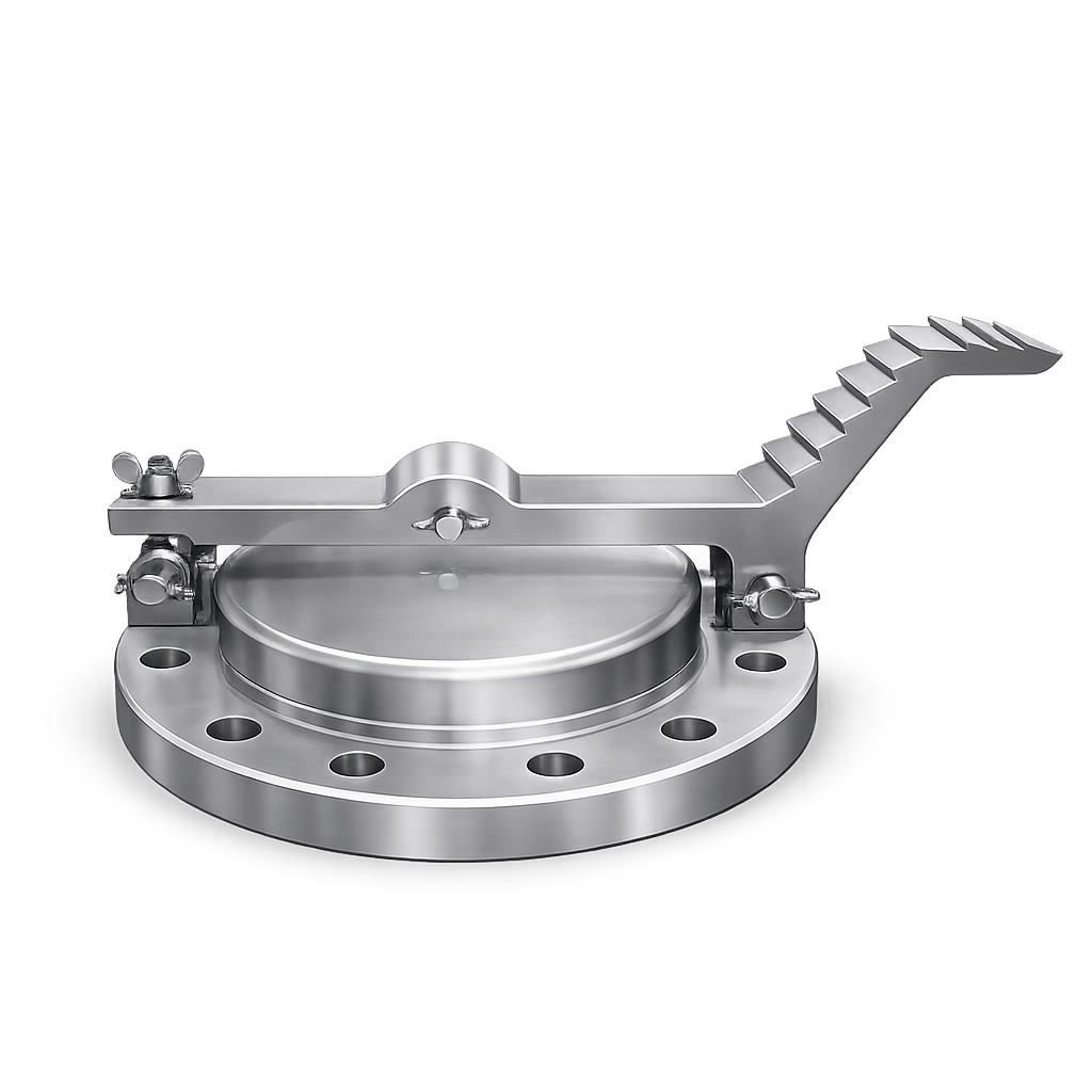
INLINE PRESSURE / VACUUM RELIEF VALVE

EFB15
  • API 2000 inline pipe-away pressure and vacuum protection
  • Weight-loaded or spring-loaded settings from 2.45 to 784 mbarg
  • For closed vents, vapour recovery lines and tank vent headers
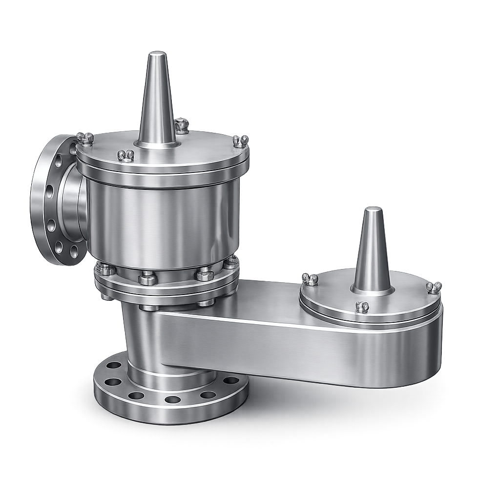
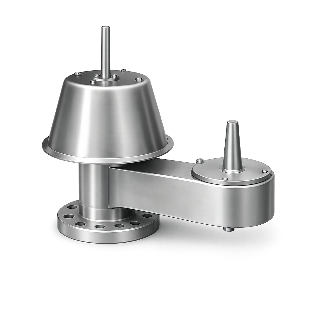
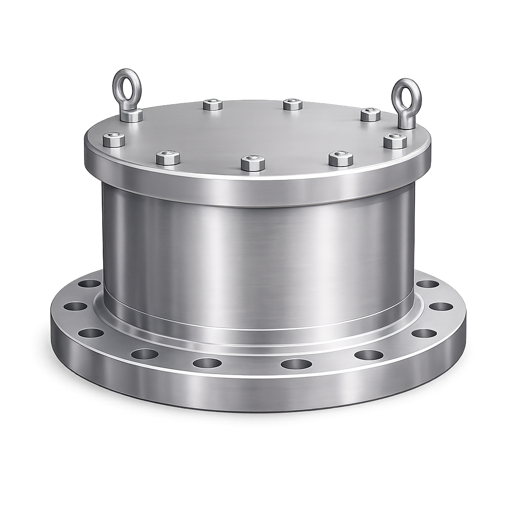
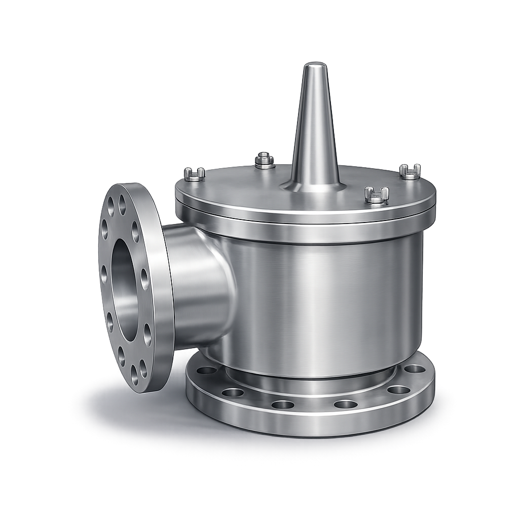
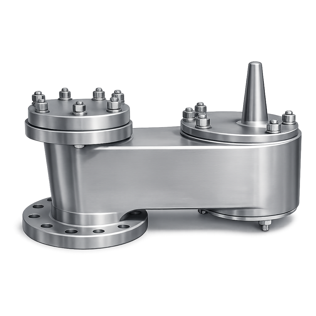
EFWB15 pressure vacuum relief and tank venting product image

Applications

Configured Service Scope
Chemical
Gas
Oil & Gas
Petrochemical
Storage Tanks

Key Specifications

NOMINAL SIZES2" to 12" (DN50 to DN300)
SETTING RANGEWeight loaded: 2.45 to 68 mbarg Spring loaded: 68 to 784 mbarg
DESIGN STANDARDAPI 2000
MATERIALSCarbon Steel / Stainless Steel / Duplex & Super Duplex
CONNECTIONSFlanged RF / FF
SEALINGSoft seat / PTFE diaphragm

Selection & RFQ Assistant

Help us identify the right solution
Guided request

Build a technical RFQ line with service data, sizing conditions, accessories and documents.

01
Service
02
Process
03
Options

FAQs

A pipe-away pressure and vacuum relief valve is installed within a venting system so that relieved vapours can be routed through connected piping rather than discharged locally at the valve. The EFB15 is an inline pressure and vacuum relief valve intended for low-pressure process piping, vapour recovery lines and tank vent headers.
Both provide pressure and vacuum relief, but their installation arrangements are different. The EFB15 is installed inline within piping or a vent header, while the EFB12 is intended for direct installation on a tank nozzle or at the end of a vent line. The correct configuration therefore depends on the vent-system arrangement as well as the pressure, vacuum and flow requirements.
Yes. Vapour recovery systems and tank vent headers are included in the published EFB15 application scope. The valve can be considered where pressure and vacuum relief must take place within connected piping. Final selection should consider the required capacity, pressure and vacuum settings and the complete vent-system conditions.
The EFB15 can be considered as part of a tank vent header or collective venting system, provided that the required pressure and vacuum capacities are established for the actual system. Where several tanks or vessels are connected to a common header, credible simultaneous venting conditions and piping pressure losses should be evaluated before final sizing.

ABOUT EFB15

The EFB15 inline pressure and vacuum relief valve is a pipe-away valve for low-pressure process piping, closed vent systems, vapour recovery lines and tank vent headers. Relieved vapours remain within connected piping instead of being discharged locally at the valve.

Designed on an API 2000 basis, the EFB15 provides controlled pressure relief and vacuum admission within the vent system. Its high-flow pallet arrangement, floating PTFE diaphragm, guided movement and soft-seat construction support dependable opening at low settings while helping retain valuable or hazardous vapours during normal operation.

The weight-loaded EFB15 covers settings from 2.45 to 68 mbarg, while the spring-loaded EFB15 covers settings from 68 to 784 mbarg. Nominal sizes range from 2 to 12 inches (DN50 to DN300), with flanged RF or FF connections.

Carbon steel, stainless steel, duplex or super duplex constructions are available for chemical, petrochemical, oil and gas, gas-handling and storage-tank duties. Protective coatings, PTFE lining or coating and combination with a flame arrester can be evaluated according to the fluid, vent-system conditions and project requirements.

Frequently Asked Questions

A pipe-away pressure and vacuum relief valve is installed within a venting system so that relieved vapours can be routed through connected piping rather than discharged locally at the valve. The EFB15 is an inline pressure and vacuum relief valve intended for low-pressure process piping, vapour recovery lines and tank vent headers.
Both provide pressure and vacuum relief, but their installation arrangements are different. The EFB15 is installed inline within piping or a vent header, while the EFB12 is intended for direct installation on a tank nozzle or at the end of a vent line. The correct configuration therefore depends on the vent-system arrangement as well as the pressure, vacuum and flow requirements.
Yes. Vapour recovery systems and tank vent headers are included in the published EFB15 application scope. The valve can be considered where pressure and vacuum relief must take place within connected piping. Final selection should consider the required capacity, pressure and vacuum settings and the complete vent-system conditions.
The EFB15 can be considered as part of a tank vent header or collective venting system, provided that the required pressure and vacuum capacities are established for the actual system. Where several tanks or vessels are connected to a common header, credible simultaneous venting conditions and piping pressure losses should be evaluated before final sizing.
The weight-loaded configuration covers pressure or vacuum settings from 2.45 to 68 mbarg. The spring-loaded configuration covers settings from 68 to 784 mbarg. The appropriate loading mechanism is determined from the required set point and operating conditions.
The EFB15 is available in nominal sizes from 2 to 12 inches, equivalent to DN50 through DN300. Final size is selected for the required pressure and vacuum venting capacities and project conditions.
The EFB15 uses API 2000 as its design basis for low-pressure venting and pressure or vacuum protection. Final sizing and configuration are checked against the actual process data and project requirements.
Available constructions include carbon steel, stainless steel, duplex and super duplex. Protective painting, special coatings, PTFE lining or PTFE coating can also be evaluated for corrosive media and demanding environments.
The floating PTFE diaphragm and soft-seat arrangement maintain a tight seal during normal operation. The valve opens only when the selected pressure or vacuum setting is reached, helping retain process vapours and reduce unnecessary evaporation losses.
Yes. A combined pressure and vacuum relief valve with flame arrester can be evaluated when the venting duty also requires flame-propagation protection. The complete assembly must be selected for the fluid, installation conditions and required capacity.
Selection requires the relief function, fluid, pressure and vacuum settings, allowable overpressure and overvacuum, separate out-breathing and in-breathing capacities, operating temperature, nominal size, flange facing, header pressure and backpressure, material and any coating, lining, flame arrester or documentation requirements.
Yes. The EFB15 can be considered for EPC and project-managed applications where pressure and vacuum settings, required venting capacities, materials, flange requirements, coatings or lining, flame-arrester requirements and documentation scope are defined during the RFQ stage. Final configuration should be confirmed against the actual process, piping and vent-system data.