This success story is presented in anonymised form. The client, plant, exact location and detailed process conditions are not disclosed.
A pharmaceutical application in Northern Europe required a pressure-vacuum relief valve capable of operating from –50 mbar vacuum to +400 mbar pressure. The equipment also had to handle chemically aggressive vapours and fit a specific piping arrangement.
The task was therefore not limited to selecting a standard valve. Pressure protection, vacuum protection, material compatibility and installation geometry had to be engineered as one complete configuration.
When standard construction is not enough
Low-pressure and vacuum protection equipment used in pharmaceutical and chemical processes may be exposed to vapours that demand more than a conventional painted carbon-steel construction. Manufacturing the complete assembly from a high-alloy material was one possible route, but it was not the only technically viable option for this service.
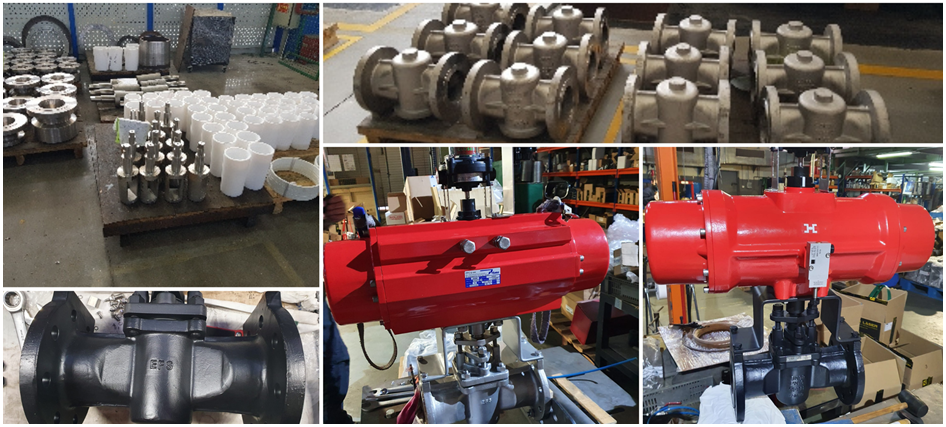
The selected material strategy retained a robust metallic valve body, used stainless-steel internal components where required and protected the surfaces exposed to the process medium with a PTFE coating. This configuration was assessed as a complete system rather than as a coating applied in isolation.
Independent pressure and vacuum protection
The required operating envelope extended to both sides of atmospheric pressure. The valve therefore incorporated two independent operating principles within the same assembly.
| Protection function | Operating principle | Project setting |
|---|---|---|
| Vacuum relief | Counterweight-operated section | –50 mbar |
| Pressure relief | Spring-loaded section | +400 mbar |
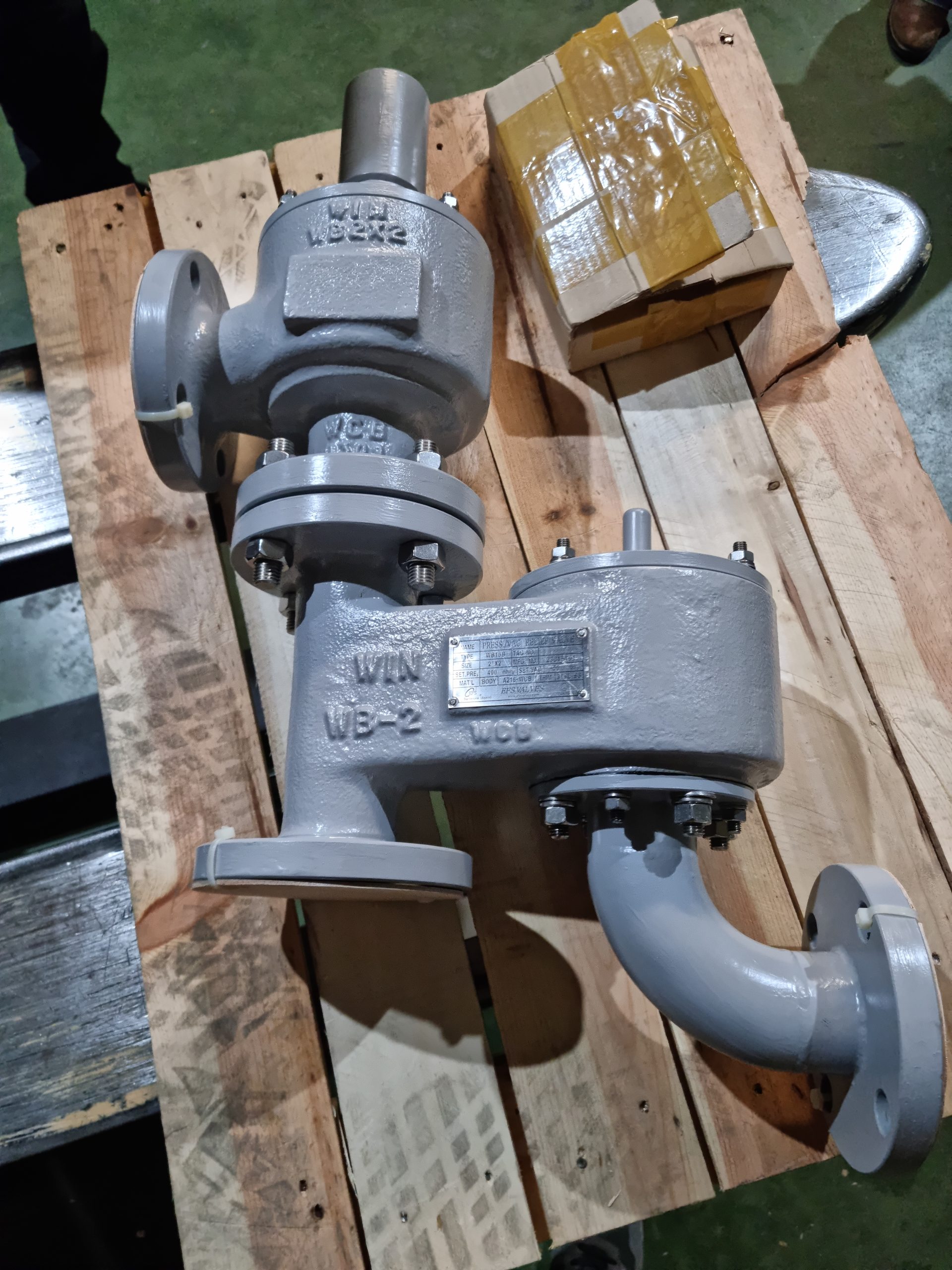
Separating the two mechanisms allowed each function to be configured for its own set point while keeping pressure and vacuum protection integrated in a single valve. The equipment could admit gas when the protected system moved into excessive vacuum and discharge vapour when its positive pressure reached the specified setting.
Adapting the vacuum inlet to the installation
The installation imposed an additional geometric constraint at the vacuum connection. A custom flanged inlet elbow was incorporated into the vacuum port to align the valve with the required piping arrangement without compromising the operation of the counterweight section.
This elbow was not treated as an unrelated site accessory. It formed part of the engineered valve assembly and was included in the dimensional and visual checks completed before delivery.
PTFE coating as part of the material strategy
For chemically aggressive vapours, corrosion resistance does not automatically require every component to be manufactured from an exotic alloy. Where the fluid, temperature, pressure and coating limitations permit, PTFE can provide an additional barrier between metallic equipment and the process medium.
In this application, the PTFE coating worked together with the metallic body construction and selected stainless-steel internals. The objective was to balance chemical resistance, mechanical integrity and the practical requirements of the pharmaceutical installation.
This choice remains application-specific. Coating suitability must be checked against the actual vapour composition, concentration, operating and cleaning temperatures, pressure cycle, surface preparation and inspection requirements.
A project-specific pressure-vacuum valve configuration
The completed equipment was manufactured as a dedicated configuration rather than selected unchanged from a standard catalogue arrangement. It incorporated:
- pressure and vacuum protection in one valve assembly;
- independent spring-loaded and counterweight-operated mechanisms;
- PTFE-coated process-exposed surfaces;
- selected stainless-steel internal components;
- a custom flanged vacuum inlet elbow; and
- project-specific connection geometry.
Manufacturing and quality checks were completed before dispatch, including dimensional verification of the assembled equipment and visual inspection of the coated surfaces. This reduced the risk of discovering incompatibilities only after the valve reached site.
Engineering takeaway
Pressure-vacuum applications involving corrosive vapours require function, materials and installation geometry to be considered together. Depending on the service, the appropriate route may be stainless steel, a special alloy, fluoropolymer-lined equipment or a metallic valve protected by a suitable coating.
The correct solution is the configuration that safely satisfies the real pressure, vacuum, chemical, mechanical and installation conditions.
Frequently asked questions
What does a pressure-vacuum relief valve protect against?
It protects a low-pressure vessel, tank or connected vent system against damaging positive pressure and excessive vacuum by discharging vapour or admitting gas at controlled set points.
Why use separate pressure and vacuum mechanisms?
Independent mechanisms allow the pressure and vacuum set points to be configured and checked separately while both functions remain integrated in one assembly.
Can PTFE coating replace a high-alloy valve body?
In some services it can form part of an effective material strategy, but it is not a universal substitute. Suitability depends on the chemical medium, concentration, temperature, pressure, cleaning regime, coating design and required inspection criteria.
Why was a custom flanged elbow used on the vacuum inlet?
The existing piping arrangement required a different inlet orientation. Incorporating the elbow into the supplied assembly provided the required geometry while preserving the operation of the vacuum relief section.
What information is needed to configure a pressure-vacuum valve?
Selection requires the pressure and vacuum set points, relieving and inbreathing capacities, vapour composition, operating and cleaning temperatures, allowable overpressure and overvacuum, materials, connections, installation orientation and any coating or documentation requirements.
Related EFSVALVES solution
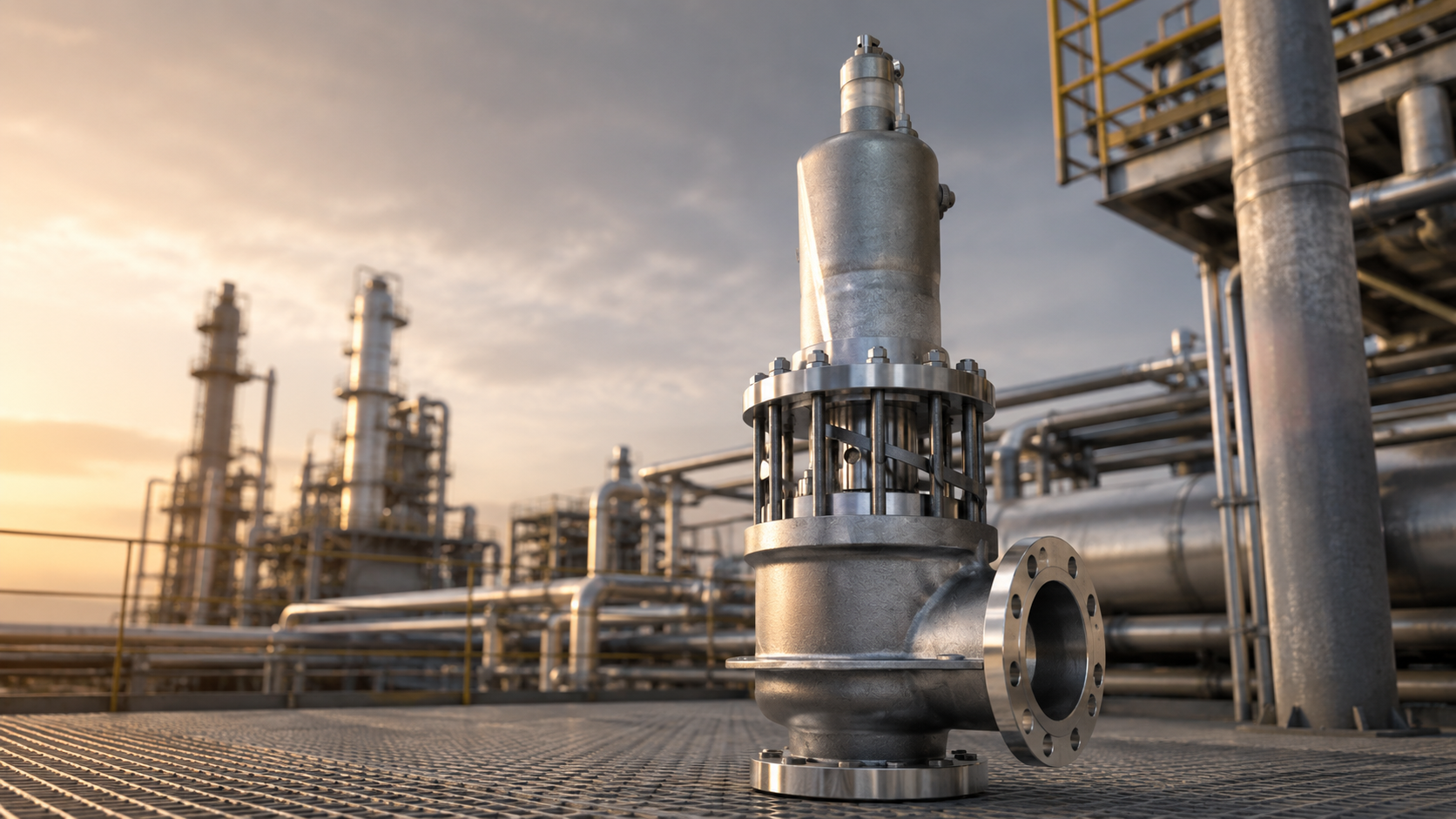
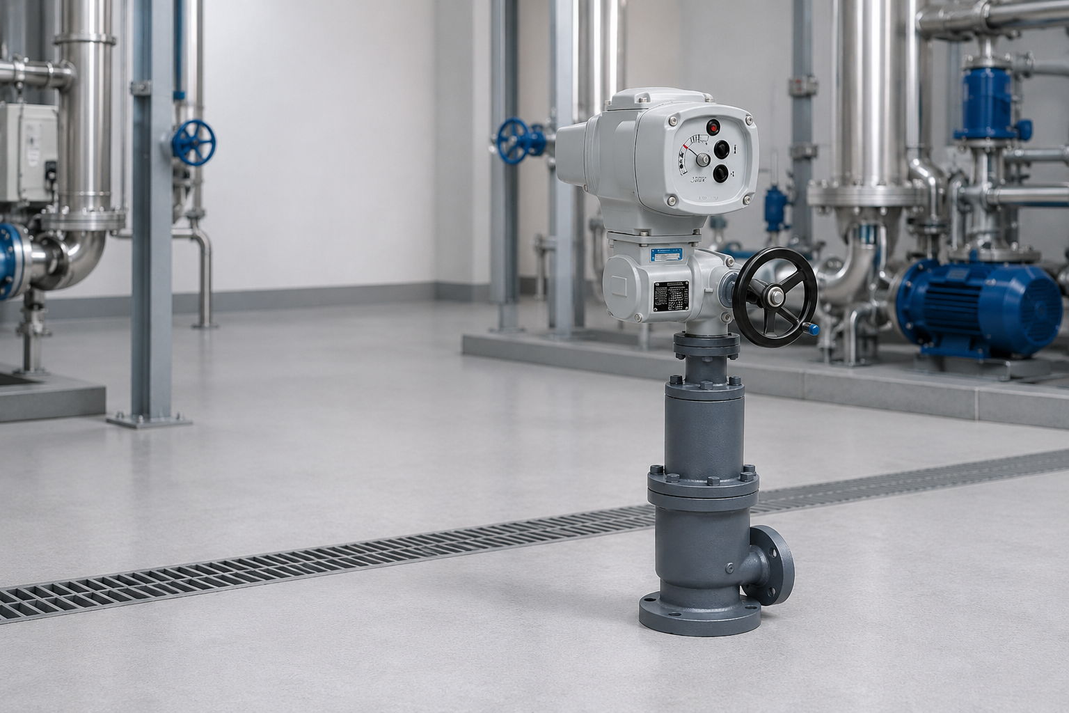
The project configuration belongs to the same application field as the EFB15 Inline Pressure / Vacuum Relief Valve. The current EFB15 platform provides pressure and vacuum protection for low-pressure piping, vapour recovery lines and vent headers, with the final materials, loading mechanism, coating and geometry selected for each duty.
Explore Tank Protection & Venting solutions →
Share the pressure and vacuum requirements, process medium and installation constraints so our engineering team can assess the appropriate configuration. Discuss your application →