IN-LINE FLAME ARRESTER

EF500DFIL
  • Flame transmission prevention
  • ATEX certified for gas explosion groups
  • Minimal pressure drop under normal flow
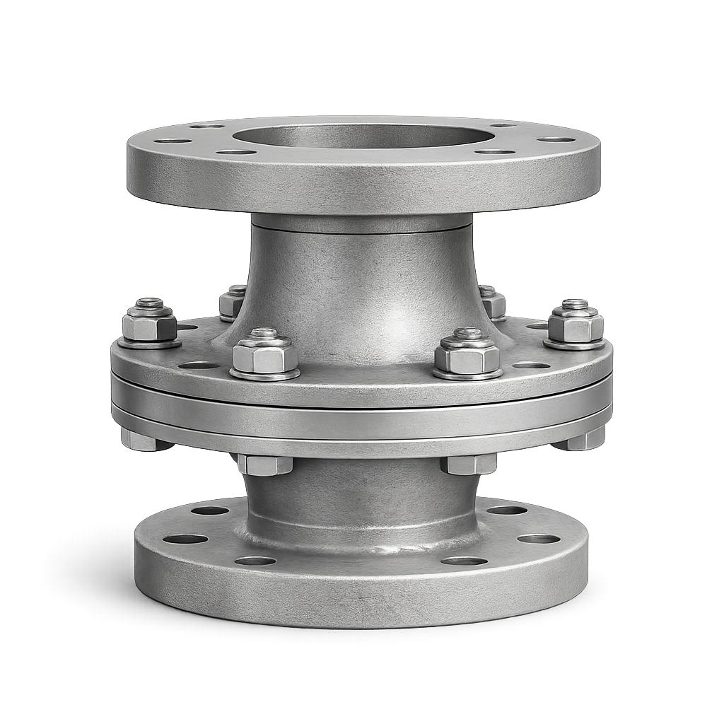
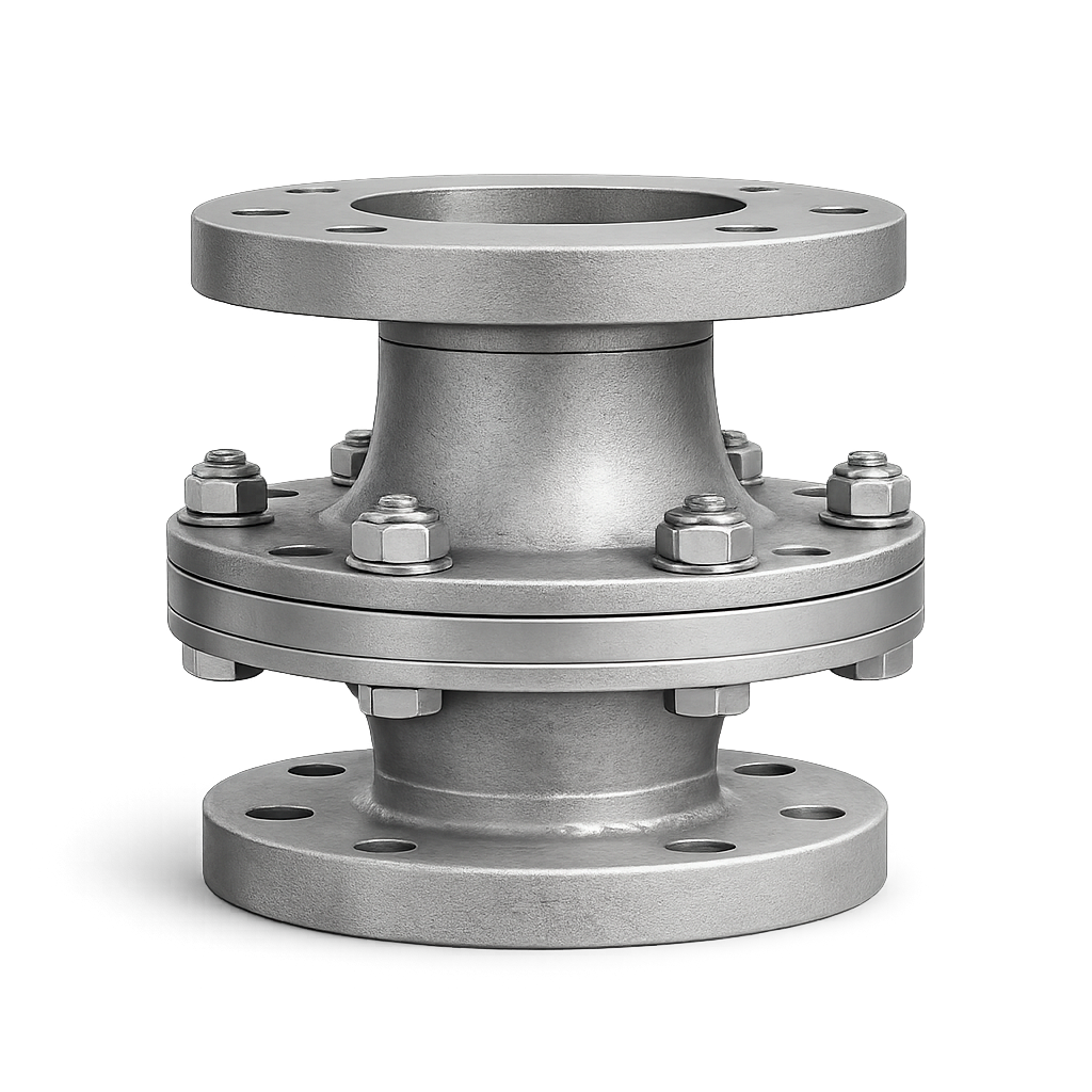
EF500DFIL in-line flame arrester

Applications

Configured Service Scope
ATEX / Hazardous Area
Chemical
Gas
Petrochemical

Key Specifications

Nominal Sizes½” to 6” / DN 15 to DN150
Flame propagationDeflagration
Explosion groupIIA / IIB1 / IIB2 / IIB3 / IIB / IIC
CertificationsATEX / PED-CE

Selection & RFQ Assistant

Help us identify the right solution
Guided request

Build a technical RFQ line with service data, sizing conditions, accessories and documents.

01
Service
02
Process
03
Options

FAQs

An in-line deflagration flame arrester is installed inside a gas or vapour piping system to help prevent flame propagation from an ignition source toward connected equipment. It can be considered where the identified explosion scenario corresponds to an in-line deflagration and the installation conditions fall within the applicable device requirements.
Yes. In-line deflagration flame arresters can form part of the protection concept for biogas and sewage-gas piping systems. Typical areas where flame-arrester protection may be considered include gas lines associated with treatment equipment, gas-consuming equipment or other potential ignition sources. Final device selection depends on gas composition, explosion group, pressure, temperature, piping configuration and possible ignition location.
Yes. Flame arresters are commonly considered within the gas systems of anaerobic digesters and wastewater-treatment plants. The correct location and type of arrester depend on the plant arrangement. Protection may be required between gas-producing or gas-storage equipment and equipment representing a potential ignition source. A plant-specific assessment is therefore necessary.
In-line flame arresters can be used as part of the protection concept for piping connected to flares, gas engines, CHP units or other gas-consuming equipment, as these can represent potential ignition sources. Whether a deflagration or detonation arrester is appropriate depends on the piping arrangement, ignition location and applicable certified installation conditions.

ABOUT EF500DFIL

The in-line deflagration flame arrester is a safety device designed to protect tanks, vessels and vent systems by preventing flame propagation into the installation during atmospheric deflagration events.

The flame arrester stops the flame front by dissipating heat through its internal flame arresting element, quenching combustion and preventing external ignition sources from entering the protected system under defined operating conditions.

The device is available in a range of nominal sizes and explosion groups, in accordance with ATEX requirements. Depending on the selected configuration, the in-line deflagration flame arrester can be applied in a wide variety of industrial installations handling flammable gases or vapours, where compliant explosion protection in vent and piping systems is required.

Frequently Asked Questions

An in-line deflagration flame arrester is installed inside a gas or vapour piping system to help prevent flame propagation from an ignition source toward connected equipment. It can be considered where the identified explosion scenario corresponds to an in-line deflagration and the installation conditions fall within the applicable device requirements.
Yes. In-line deflagration flame arresters can form part of the protection concept for biogas and sewage-gas piping systems. Typical areas where flame-arrester protection may be considered include gas lines associated with treatment equipment, gas-consuming equipment or other potential ignition sources. Final device selection depends on gas composition, explosion group, pressure, temperature, piping configuration and possible ignition location.
Yes. Flame arresters are commonly considered within the gas systems of anaerobic digesters and wastewater-treatment plants. The correct location and type of arrester depend on the plant arrangement. Protection may be required between gas-producing or gas-storage equipment and equipment representing a potential ignition source. A plant-specific assessment is therefore necessary.
In-line flame arresters can be used as part of the protection concept for piping connected to flares, gas engines, CHP units or other gas-consuming equipment, as these can represent potential ignition sources. Whether a deflagration or detonation arrester is appropriate depends on the piping arrangement, ignition location and applicable certified installation conditions.
Yes. For an in-line deflagration flame arrester, the distance between the possible ignition source and the arrester is an important installation parameter. The permissible arrangement depends on the specific certified configuration, explosion group and piping geometry. For this reason, ignition location and relevant pipe arrangement should be provided during selection.
A detonation flame arrester should be considered where the piping arrangement and credible combustion scenario cannot be adequately covered by the certified conditions of an in-line deflagration arrester. Longer or more complex piping and the location of potential ignition sources can influence flame acceleration. The final selection must be based on the actual installation and applicable certification, not only on pipe diameter or gas type.
A deflagration and a detonation involve different combustion and flame-propagation behaviour. In confined piping, a flame can accelerate under certain conditions and may develop from a deflagration into a detonation. This difference is fundamental to flame-arrester selection because the device must be suitable for the explosion scenario identified for its installation.
The explosion group must be based on the actual gas composition and applicable classification. Biogas and biomethane streams are often methane-rich, but their composition can vary. The relevant gas composition or specified explosion group should therefore be provided when selecting the EF500DFIL.
MESG, or Maximum Experimental Safe Gap, is used in the classification of flammable gases and vapours and is related to their flame-transmission characteristics. The applicable explosion group is an important input when selecting the appropriate flame arrester configuration.
Yes. Wet biogas and sewage gas can contain moisture and condensate. Accumulation of liquids or contamination can affect the flame-arrester element and flow path, so this should be considered in the installation, inspection and maintenance concept. The EF500DFIL should not be assumed to be self-draining unless the specific selected configuration confirms this characteristic.
Yes. The flame-arresting element creates resistance to gas flow. Pressure drop should therefore be evaluated against the required gas flow rate and available system pressure, particularly in low-pressure biogas and renewable-gas systems.
The main information normally required includes: gas or vapour; gas composition; required explosion group, if specified; required flow rate; operating and design pressure; operating and design temperature; pipe size and connection; possible ignition source; distance and piping arrangement between ignition source and arrester; and applicable project specifications. These data are important to distinguish between a suitable in-line deflagration configuration and a potentially different protection requirement.
Delivery time depends on the selected size, material, explosion group, configuration, quantity and project requirements. The applicable delivery time is confirmed for each quotation. Logistics and international delivery can be coordinated according to the agreed scope.
Any customer or third-party inspection requirements should preferably be identified during the RFQ stage so that their scope can be evaluated and agreed.
Yes. The EF500DFIL can be considered for EPC and project-managed supplies where defined technical, quality, inspection and documentation requirements apply. The applicable project requirements should be identified during quotation.
Documentation is defined according to the selected device and agreed project scope. Product, material, inspection and test documentation applicable to the selected configuration can be included as agreed. Any specific certification, traceability or additional project requirements should be defined at RFQ stage.